Share cost-effective products and high-quality services with customers. Contact Us


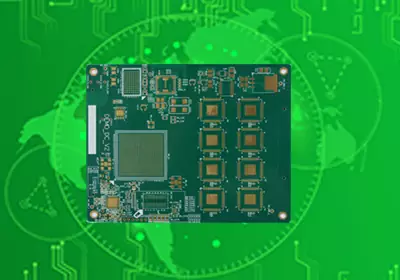
A capacitor for circuit board applications must match the electrical demands of the circuit, not just the capacitance value shown on a schematic. Engineers need to consider operating voltage, effective capacitance, ESR, ripple current, temperature, and PCB layout before choosing a component. A poorly selected capacitor can cause excessive power ripple, unstable voltage regulation, signal distortion, or premature component failure, even when the rest of the circuit is designed correctly.
The selection process starts by identifying the capacitor's role. A microcontroller power pin needs local decoupling to handle rapid changes in current. A voltage regulator may require output capacitors with specific electrical characteristics to remain stable. An analog signal path may need a capacitor that preserves the required frequency response, while a power input may require bulk capacitance to absorb slower changes in load demand. Each application has different priorities, so a single capacitor type or value cannot suit every PCB circuit board.
Choosing the Right Capacitor Type
Ceramic capacitors are widely used in PCB designs because they are compact, readily available in surface-mount packages, and suitable for decoupling and high-frequency filtering. Their low ESR makes them useful for many digital and power circuits. However, high-capacitance ceramic components using X5R or X7R dielectric can lose a significant amount of effective capacitance under DC bias. Before selecting a part for a 3.3 V or 5 V power rail, engineers should check the manufacturer's capacitance-versus-voltage data to ensure the component provides sufficient capacitance at its actual operating voltage.
Aluminum electrolytic capacitors are commonly used for bulk energy storage and power supply smoothing. They offer high capacitance at a relatively reasonable cost, making them useful near power inputs and voltage regulators. Their selection requires attention to ripple-current capability, ESR, operating temperature, and expected service life. High temperatures and excessive ripple current can accelerate degradation, particularly in applications that operate continuously.
Tantalum capacitors can provide high capacitance in compact packages, making them suitable for selected power-management applications where board space is limited. Their voltage derating, surge-current tolerance, polarity, and failure characteristics must be evaluated carefully. A tantalum capacitor should not be substituted for another technology simply because its capacitance and voltage ratings appear similar.
Film capacitors are useful when stable electrical characteristics, low distortion, or specific voltage and frequency performance are required. They can be appropriate for precision signal circuits, filtering, and certain power-electronics applications. However, their physical size may make them less suitable for compact, high-density PCB layouts.
The right capacitor for circuit board design depends on the function it must perform. Ceramic capacitors are often preferred for local high-frequency decoupling, electrolytic capacitors for bulk energy storage, and film capacitors for applications requiring particular stability characteristics. These are general starting points rather than fixed rules; the circuit requirements and component datasheets should determine the final choice.
Check Capacitance and Voltage Rating Under Real Conditions
Nominal capacitance does not always represent the capacitance available in an operating circuit. This is particularly important when selecting multilayer ceramic capacitors for power rails. A compact ceramic capacitor marked 10 µF may provide considerably less than 10 µF at its working voltage, depending on its dielectric, package size, and rated voltage.
This difference matters when a capacitor supports a processor, communication IC, or switching regulator during a sudden change in current demand. If its effective capacitance is too low, the supply voltage may fluctuate more than expected. Engineers should therefore evaluate the manufacturer's DC-bias characteristics rather than selecting a component based only on its nominal value.
Voltage rating also requires adequate margin. The selected capacitor must tolerate the maximum voltage it will experience, including relevant ripple, startup conditions, and transient overshoot. A component rated close to the normal supply voltage may not provide sufficient protection against foreseeable voltage spikes.
The appropriate margin depends on the capacitor technology, operating environment, and manufacturer's recommendations. Ceramic capacitors require particular attention to DC-bias effects, while electrolytic capacitors also need careful evaluation of ripple heating and lifetime. For tantalum capacitors, surge conditions and recommended voltage derating are especially important.
Capacitance tolerance should also match the application. General-purpose power filtering may tolerate wider variation, whereas precision filters, timing circuits, and frequency-sensitive designs may require more stable components.
Evaluate ESR and Ripple Current for Power Circuits
Equivalent series resistance (ESR) affects the voltage ripple, heat generation, and transient response of a capacitor. A capacitor with excessive ESR may perform poorly in a switching power supply, even if its nominal capacitance is correct. However, choosing the lowest-ESR component available is not always the right approach.
Some voltage regulators require an output capacitor within a specified ESR range to maintain control-loop stability. Replacing a recommended electrolytic capacitor with a low-ESR ceramic component can change the regulator's behavior. Before making a substitution, engineers should check the regulator datasheet for supported capacitor types, capacitance requirements, and stability conditions.
Ripple-current capability is another important consideration. Current flowing through a capacitor's internal resistance generates heat, which can accelerate aging and reduce service life. This is particularly relevant to power supplies, DC-DC converters, and circuits exposed to continuous load fluctuations.
When selecting capacitors for these applications, engineers should compare the expected ripple current with the component's rated capability under the intended operating conditions. Temperature derating and lifetime specifications should be reviewed alongside ESR and capacitance. For designs with demanding transient loads, testing the completed power circuit can reveal voltage fluctuations that are not apparent from component ratings alone.

Place Decoupling Capacitors Close to the Relevant IC Pins
Capacitor placement directly affects how effectively a PCB board handles high-frequency current changes. The traces, pads, and vias connecting a capacitor introduce parasitic inductance and resistance. At high frequencies, these effects can prevent a capacitor from responding effectively to fast switching demands.
For local decoupling, place the capacitor close to the IC power pin it supports. Keep the connection between the power pin, capacitor, and ground as short and direct as the layout allows. The goal is to minimize the current-loop area and provide a low-inductance path for transient current.
Ground routing is just as important as the distance between the capacitor and the IC. A capacitor positioned close to a chip may still provide limited benefit if its ground connection follows a long trace or an indirect return path. Where the stackup permits, a nearby ground-plane connection and appropriately positioned via can help reduce loop inductance.
The required placement depends on the package, PCB layer arrangement, and current path. For high-speed digital circuits, designers should follow the IC manufacturer's decoupling recommendations and avoid routing the capacitor's return current through unnecessary portions of the ground network. In RF and sensitive analog designs, the placement must also account for unwanted coupling and interference with nearby signal paths.
Bulk capacitors serve a different purpose from small local decoupling capacitors. They are generally placed near a power input, voltage regulator, or group of loads to support slower current changes and reduce supply fluctuations. The local decoupling network and bulk capacitance should be designed together, with each component serving a defined role.
Adding more capacitors does not automatically improve power integrity. Capacitors with different values and parasitic characteristics can interact with the PCB power distribution network and create impedance peaks. High-speed and high-current designs may require power integrity analysis or measurement to confirm that the selected capacitor network performs as intended.
Select Capacitors for Signal Filtering and Coupling
In signal circuits, the correct capacitor depends on the required frequency response and the impedance of the surrounding components. A coupling capacitor passes changing signals between circuit stages while blocking DC. If its capacitance is too small for the circuit's input and output impedances, it may attenuate low-frequency signals that should pass through unchanged.
Filter capacitors require similar attention. Their capacitance, tolerance, dielectric characteristics, and interaction with resistors or inductors determine which frequencies are attenuated or preserved. For general-purpose filtering, a standard ceramic capacitor may be sufficient. Precision analog circuits may require components with better capacitance stability and lower leakage.
Oscillators and timing circuits introduce additional requirements. Capacitance variation, temperature drift, leakage, and parasitic effects can change timing accuracy or oscillation frequency. In crystal oscillator circuits, the load capacitance must follow the oscillator manufacturer's recommendations and account for the surrounding PCB parasitics.
Engineers should therefore evaluate the capacitor as part of the complete signal path rather than treating it as an independent component. A part that works well in a power supply may not provide the stability or frequency response required in an analog or timing circuit.
Prevent Capacitor Problems During PCB Assembly
Capacitor reliability depends on component selection, PCB design, and assembly quality. Incorrect polarity, unsuitable footprints, excessive soldering temperatures, and mechanical stress can all contribute to defects.
Polarized electrolytic and tantalum capacitors must be oriented correctly during placement and soldering. Incorrect polarity can cause leakage, overheating, or failure. The PCB footprint should follow the manufacturer's recommended land pattern to support reliable solder-joint formation and avoid unnecessary mechanical stress.
Multilayer ceramic capacitors require particular care because their ceramic bodies can crack when subjected to board bending. Depanelization, connector insertion, enclosure installation, and rough handling may introduce mechanical stress. Where practical, avoid placing larger ceramic capacitors in high-stress areas near board edges or separation lines. Appropriate depanelization methods and controlled handling can further reduce the risk of cracking.
Reflow soldering conditions must remain within the component manufacturer's specified limits. When substituting a capacitor during production, verify not only capacitance and voltage rating but also package dimensions, dielectric type, ESR, ripple-current capability, and application compatibility.
Inspection and testing should reflect the circuit's risks. Power circuits may need ripple-voltage, load-transient, temperature, and regulator-stability checks. Signal circuits may require noise or frequency-response measurements. Production inspection should confirm component placement, polarity where applicable, and solder-joint quality.
Establish a Reliable Capacitor Selection Process
A reliable capacitor for circuit board design begins with a clear understanding of the electrical requirement. Identify whether each component provides local decoupling, bulk energy storage, output filtering, signal coupling, or timing. Then determine the required capacitance, operating voltage, frequency range, temperature range, ripple-current capability, and expected service life.
Next, verify the actual performance of the selected component using its datasheet. Check DC-bias characteristics for ceramic capacitors, ripple-current and lifetime ratings for electrolytic types, and surge-current and voltage derating guidance for tantalum components. For switching regulators, confirm that the capacitor meets the manufacturer's stability requirements.
The PCB layout must then support the capacitor's intended function. Keep high-frequency decoupling loops short, provide an effective ground-return path, and position bulk capacitors according to the power distribution path. For sensitive signal circuits, evaluate capacitance stability and parasitic effects that could alter the intended response.
Finally, validate the completed PCB board under representative operating conditions. Check for unexpected voltage ripple, unstable regulation, excessive heating, signal degradation, or assembly defects before releasing the design for production.
Choosing the right capacitor for circuit board applications requires more than matching a nominal value to a schematic. By considering component characteristics, operating conditions, PCB layout, and manufacturing quality together, engineers can improve power stability, reduce unwanted noise, and achieve more reliable electronic assemblies.