Share cost-effective products and high-quality services with customers. Contact Us


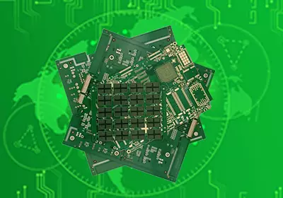
What is a circuit board fuse holder?A circuit board fuse holder is a mounting component that connects a fuse to the copper circuit of a PCB. The holder usually contains conductive contacts or terminals that connect the fuse ends with the board traces.
Compared with soldering a fuse directly onto a PCB board, a circuit board fuse holder allows easier replacement after a protection event. This is especially useful in equipment where maintenance access is required or where fuse replacement is part of the product service process.
Cirucit board fuse holders are available in different structures, including through-hole fuse holders, surface mount fuse holders, and PCB fuse clips. Through-hole versions use pins inserted into drilled holes and soldered to the PCB, providing strong mechanical support. Surface mount versions are designed for SMT assembly and are suitable for compact PCB layouts. Fuse clips provide a simpler mounting method by holding the fuse directly through conductive contacts.
The choice of fuse holder depends on the electrical requirements, available PCB space, production method, and whether the fuse needs to be replaced frequently.
PCB Layout Considerations for Fuse Holder Design
The placement of a circuit board fuse holder directly affects circuit protection performance. In many designs, the fuse holder is located close to the power input area or near the circuit section that requires protection. This reduces the length of the power path before the fuse and limits the amount of unprotected circuitry.
The PCB traces connected to the fuse holder also require careful consideration. The copper width and thickness need to support the expected current without creating excessive resistance or heat. A mismatch between fuse rating and PCB conductor capacity can reduce the effectiveness of the protection design.
Thermal conditions should also be evaluated during placement. A fuse may generate heat when operating near its rated limit or during fault conditions. If it is located too close to high-temperature components, the surrounding environment may influence its performance.
Mechanical access is another important factor. In applications where the fuse may need replacement, the design should provide enough space for inspection and removal. The enclosure, nearby components, and PCB edge position can all affect whether maintenance can be performed easily. Some fuse holders are designed for edge mounting or elevated installation to improve accessibility.
For this reason, fuse holder placement should be considered during PCB layout planning rather than added after routing has already been completed.

Types of PCB Fuse Holders and Their Applications
Through hole PCB fuse holders are commonly used in applications where mechanical strength and serviceability are important. Their leads pass through PCB holes and are soldered to the circuit board, creating a stable connection that can withstand mechanical stress.
Surface mount fuse holders are suitable for compact electronic assemblies where automated SMT production is preferred. Their smaller footprint allows more flexible component placement, although the PCB footprint and soldering process must be carefully designed to maintain connection reliability.
Circuit board fuse clips provide another mounting option for cylindrical fuses. They occupy relatively little board space and allow the fuse to be replaced without removing solder connections. However, designers need to consider mechanical retention, environmental protection, and insulation requirements according to the application conditions.
The selected fuse holder type also affects PCB assembly requirements. Through-hole components require drilled holes and may involve wave soldering or selective soldering processes. Surface mount versions require suitable land patterns, solder paste design, and reflow process control.
Therefore, fuse holder selection should be considered together with the PCB manufacturing process rather than as an isolated component choice.
Manufacturing and Reliability Considerations for Circuit Board Fuse Holders
A reliable circuit board fuse holder design requires coordination between schematic design, PCB layout, component selection, and assembly processes.
The PCB footprint must match the fuse holder specification accurately. Incorrect pad dimensions, insufficient spacing, or unsuitable soldering conditions may reduce mechanical strength and affect electrical reliability.
Clearance around the fuse holder should also be considered. During a fault condition, the fuse may experience elevated temperatures. Proper spacing from sensitive components can help reduce the impact of heat generated during operation.
Electrical testing is another part of verifying fuse protection. During PCB assembly inspection and testing, the connection between the fuse holder and circuit should be checked to ensure proper continuity and stable electrical performance.
For larger electronic systems, fuse protection is usually part of the overall power distribution design. Fuse selection, PCB copper design, connector capacity, power supply characteristics, and protected circuit requirements need to work together to achieve the intended protection function.
A circuit board fuse holder is therefore an interface between the protection component and the PCB system. Its mechanical structure, electrical connection, and position on the board all influence the reliability of the final assembly.
A circuit board fuse holder provides a practical way to integrate fuse protection into a PCB assembly. By allowing the fuse to be securely mounted and replaced when necessary, it supports both circuit protection and maintenance requirements.The design process involves selecting a suitable holder type, defining the correct PCB footprint, managing current paths, considering thermal conditions, and ensuring compatibility with the manufacturing process.A properly designed fuse holder implementation helps improve the reliability of electronic assemblies while maintaining easier serviceability throughout the product lifecycle.