Share cost-effective products and high-quality services with customers. Contact Us


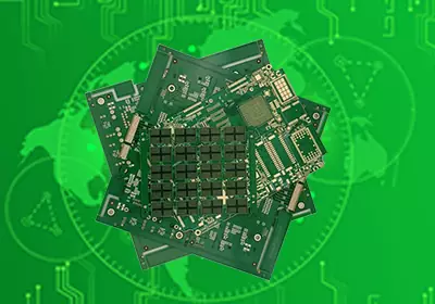
Circuit board mounting determines how a printed circuit board is secured inside an electronic product and how it interacts with the surrounding enclosure. The right mounting method helps maintain board alignment, control mechanical stress, protect electrical connections, and support heat dissipation. Without proper support, vibration, fastener pressure, or enclosure misalignment can damage components and solder joints. A reliable mounting design therefore considers the PCB, its mounting hardware, and the complete product structure together.
Choosing the Right PCB Mounting Method
Different products require different ways to secure a circuit board. Screws and standoffs provide stable support and maintain a defined gap between the PCB and the enclosure. Standoffs can be metallic or insulating, depending on the required strength, grounding arrangement, and electrical isolation. Their height must accommodate underside components, solder joints, and necessary airflow.
Other PCB mounting methods include card guides, rails, clips, molded bosses, brackets, and adhesives. Rails are useful for boards installed in industrial equipment, while clips can simplify assembly in compact electronic devices. Adhesive supports may work for lightweight applications, provided the material can withstand expected temperatures, vibration, and aging.
Selecting a mounting solution involves more than matching the board dimensions. Designers should consider PCB weight, component height, connector insertion forces, enclosure materials, assembly sequence, and future maintenance. A small sensor board may need only a few supports, whereas a power board with heavy components may require additional reinforcement to limit movement and bending.
Mounting Holes and Electrical Clearances
Mounting holes must be planned alongside copper routing and enclosure geometry. Non-plated holes are commonly used when fasteners need to remain electrically isolated from the circuit. Plated holes may be appropriate when an intentional electrical connection is required. The hole type should be clearly specified in the PCB design and manufacturing documentation.
Copper keep-out areas can prevent screws, washers, and metal standoffs from contacting unintended conductors. Designs involving hazardous voltages must also maintain the required electrical clearance and creepage distances for their operating conditions and applicable safety standards. If the board needs to connect to a metal chassis for grounding or electromagnetic compatibility, the bonding method should be defined rather than relying on accidental contact with mounting hardware.
Dimensional tolerances are equally important. Differences between PCB hole positions, enclosure bosses, and fastener locations can make assembly difficult or force the board to bend. The mounting layout should allow the board to fit without excessive stress while keeping connectors aligned with enclosure openings. These checks are particularly important when the circuit board is assembled into a tightly constrained product.

Preventing Mechanical Stress and Heat Problems
A secure circuit board mounting arrangement distributes mechanical loads without putting unnecessary pressure on the PCB. Excessive screw torque, uneven supports, or misaligned holes can bend the board and stress solder joints, vias, and connector interfaces. Over time, vibration or repeated movement can turn these stresses into electrical failures.
Heavy components and external cables require particular attention. Components positioned far from a support point may experience greater mechanical loads during shock or vibration. Additional supports or retention brackets can reduce movement, while cable strain relief helps prevent pulling forces from reaching board-mounted connectors.
Thermal management also influences mounting decisions. The gap between a PCB and its enclosure affects airflow, while a deliberately designed contact with a chassis or heat spreader can help transfer heat away from power components. Thermal pads and clamps must fit correctly and avoid excessive pressure on the board. A solution that improves cooling in one area should not introduce bending or interfere with nearby components.
For this reason, circuit board mounting should be evaluated as part of the complete mechanical and thermal design, not as a separate fastening task.
Testing the Complete Installation
Before production, engineers should verify that the PCB fits the actual enclosure and that mounting hardware does not interfere with components, connectors, cables, or service access. A three-dimensional mechanical review can identify collisions and dimensional problems before they become costly assembly issues.
Prototype testing should confirm that the board sits flat, fasteners engage correctly, connectors align, and exposed conductors remain safely separated from metal hardware. Grounding and chassis connections should also be checked for consistent electrical contact. Products exposed to significant vibration, shock, or temperature variation may require additional validation under representative operating conditions.
Manufacturing documents should specify hole dimensions, plating requirements, copper keep-out zones, hardware types, board-to-enclosure spacing, and grounding requirements. Clear instructions help PCB fabrication, assembly, and enclosure production follow the same design intent.
Ultimately, effective circuit board mounting keeps the board securely positioned while controlling mechanical loads, preserving electrical clearances, and accommodating thermal requirements. By selecting suitable supports, designing mounting holes carefully, and validating the installed assembly, engineers can improve product durability and reduce avoidable failures throughout the PCB's service life.