Share cost-effective products and high-quality services with customers. Contact Us


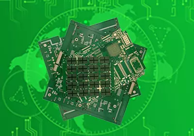
A FPC cable is a flexible printed circuit used to carry electrical signals or power through compact electronic assemblies. Unlike a conventional cable made from individual wires, A FPC uses patterned copper conductors formed on a flexible substrate. This allows the circuit to follow a defined shape, pass through narrow spaces, and connect components that may not be aligned on the same plane.
FPC cables are commonly used where a rigid PCB or conventional wire harness would take up too much space or make assembly more complicated. The flexible structure can be designed with bends, openings, connector contacts, stiffened sections, and different circuit patterns to suit the mechanical layout of the product. FPCs can also use multiple conductive layers when the application requires more complex routing or higher circuit density.
Because FPC cable and FFC cable are often used for similar interconnection purposes, the two terms are sometimes treated as interchangeable. Their construction, however, is different. Understanding that difference is important when selecting a flexible interconnect or defining a new PCB design.
What is A FPC Cable
FPC cable stands for Flexible Printed Circuit cable. It is essentially a flexible circuit that performs the role of an electrical interconnect. Copper foil is patterned to form the required traces on a flexible dielectric substrate, with protective coverlay or other insulation used to protect the circuit. Depending on the design, the FPC can contain one or more conductive layers, plated connections, exposed contact areas, and reinforced connector sections.
The main advantage of this construction is design freedom. Unlike a cable made from fixed parallel conductors, A FPC can route traces around mechanical features and change the shape of the circuit to match the product. Different traces can also be assigned to power, ground, analog signals, digital signals, or other electrical functions within the same flexible structure.
Connector areas often require additional mechanical support. A stiffener can be added behind the contact region to provide the thickness and rigidity required for insertion into a connector. The connector interface and exposed contact geometry therefore need to be designed together with the FPC itself.
A FPC can also be more than a simple connection between two boards. Depending on its construction, electronic components can be mounted directly onto the flexible circuit. This makes FPC suitable for assemblies where the interconnect and part of the electronic circuit need to occupy the same compact space.

FPC Cable vs FFC Cable
The difference between FPC cable and FFC cable begins with how the conductors are made. An FFC, or Flexible Flat Cable, normally consists of parallel flat conductors arranged at a defined pitch and laminated between insulating films. The conductors generally run straight from one end of the cable to the other.
A FPC is manufactured more like a printed circuit board. Copper is patterned on a flexible substrate, allowing the conductor layout to include changes in direction, different widths, branches, and more complex circuit structures. FPCs can also incorporate vias and multiple conductive layers when required by the design.
This difference affects how each type is used. FFC is well suited to straightforward point-to-point connections where the conductors can remain parallel. FPC is more useful when the interconnect must follow a customized mechanical path or when the flexible section needs additional circuit functionality.
The two technologies can use similar connector systems, which is one reason they are often confused. Both may be designed for compact board-to-board or board-to-module connections, but the connector must match the contact arrangement, thickness, pitch, and termination structure of the selected cable or flexible circuit.
The choice therefore should not be based only on appearance. The electrical routing, mechanical path, bending requirements, connector interface, available space, and assembly process all need to be considered before deciding between FPC and FFC.
FPC Cable Design Considerations
The mechanical behavior of A FPC cable is closely connected to its electrical design. A flexible section that bends repeatedly can place stress on copper traces, plated features, and transitions between flexible and reinforced areas. The bend location, bending direction, construction thickness, and expected movement should therefore be defined before the circuit layout is finalized.
Trace routing through a bend area also requires care. Sharp changes in geometry can create localized mechanical stress, while unnecessary features in a repeatedly flexed region can reduce reliability. For dynamic applications, the selected copper and flexible material system should be compatible with the expected movement and environmental conditions.
The connector end requires particular attention because it may be inserted into a ZIF or similar connector. The exposed contact pattern must match the connector, while the contact area may require a stiffener to maintain the required mechanical characteristics. Contact finish, pad dimensions, cable thickness, and connector orientation should all be checked as one interface rather than as separate design details.
Electrical requirements can also influence the FPC structure. High-speed signals may require controlled impedance, an appropriate reference structure, and careful spacing between conductors. Ground conductors or shielding structures may be incorporated when electromagnetic compatibility or signal integrity requires them. The exact construction depends on the electrical requirements and the mechanical constraints of the product.
FPC cables can be designed in different shapes to fit around housings, displays, batteries, hinges, sensors, or other components. This flexibility is one of their main advantages, but the finished shape must still be compatible with fabrication, assembly, bending, and inspection requirements.
FPC Cable Applications and Manufacturing
FPC cables are used in electronic products where compact interconnections and flexible routing are required. Typical applications include displays, cameras, portable electronics, automotive electronics, sensors, printers, industrial equipment, and other assemblies where conventional wiring would occupy more space or make routing difficult. FFCs are also widely used in these types of products, particularly where a simple parallel connection is sufficient.
Manufacturing A FPC cable generally involves preparing the flexible substrate and copper material, forming the required circuit pattern, creating plated features where necessary, applying protective coverlay, forming the final profile, finishing contact areas, and inspecting the completed circuit. The actual process depends on whether the FPC is single-sided, double-sided, multilayer, or includes additional rigid sections.
Electrical testing is important because A FPC can contain fine traces and closely spaced contact features. Continuity and isolation testing can verify the basic electrical connections, while dimensional inspection can confirm the outline, contact position, holes, stiffeners, and other critical features.
The mechanical design should be validated as well. A FPC that passes an electrical test may still have problems if its bend radius, connector transition, or mounting arrangement does not match the product assembly. For applications involving repeated movement, the expected flexing conditions should be considered during design validation rather than relying only on a static electrical test.
A FPC cable is therefore best understood as a flexible printed circuit designed to perform an interconnection function. Its patterned copper structure provides considerably more routing freedom than a conventional flat cable, while its flexible construction allows the circuit to fit into compact and mechanically constrained assemblies. The distinction between FPC and FFC becomes particularly important when the product requires customized routing, complex circuit structures, or a flexible section that must integrate more closely with the surrounding electronics.