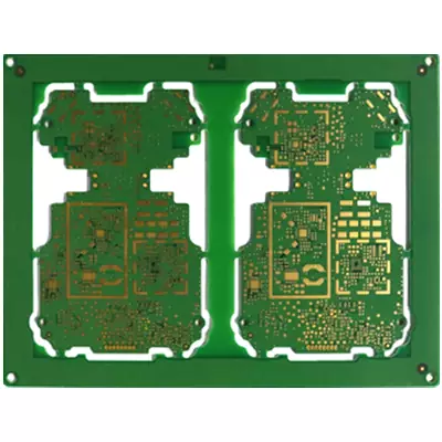
Product Name:HDI PCB
Material:Shengyi, Tuc, ITEQ, Panasonic
Thickness: 0.3-3.2mm
Copper thickness: 0.5OZ/1oz
Surface technology: Enig/Osp
Solder mask: Green/White/Black/Red/Blue
Silk screen: White
Minimum line width/spacing: 6/6mil
Minimum through-hole: Bga 2mil
Application: HDl circuit board
HDI pcb is circuit board manufactured using high-density microfabrication and tiny vias, also known as High Density Interconnector (HDI) boards, which utilise microblind embedded vias to achieve high density distribution. It uses micro blind buried hole technology to achieve a high density of line distribution, HDI pcbare composed of an inner layer of lines and outer layer of lines, through the drilling holes and holes in the metallisation process, so that the lines of each layer can be connected to each other internally.
HDI pcb is commonly prepared using the layer-by-layer method, and the more layers in the layer-by-layer process, the higher the technical level of the board. Generally speaking, the ordinary HDI circuit board using a layer, and high-level HDI will be used two or more times the layer technology, and will also be integrated into the stacked holes, plating to fill the holes, laser direct hole punching and other advanced PCB technology.
When the number of PCB layers exceeds eight, the cost of manufacturing using the HDI process is lower compared to the traditional complex lamination process. In addition, HDI board is more conducive to the application of advanced packaging technology, its electrical performance and signal accuracy is more superior than the traditional PCB. At the same time, HDI pcb in the radio frequency interference, electromagnetic wave interference, electrostatic discharge and thermal conductivity and other aspects of the performance has also been significantly improved.
HDI pcb manufacturing process
Compared with ordinary PCBs, the manufacturing process of HDI pcb is more complicated, which covers the following key technologies:
Microvia and Blind Via (Microvia/Blind Via) process:
Microvia: These tiny holes, usually in the range of 3 mil (~0.076 mm) to 5 mil (~0.127 mm) in diameter, are precisely created by laser or mechanical drilling. The microvia process allows for exceptionally tight connections on PCBs.
Blind holes: These holes only penetrate the outer and inner layers of the PCB and are commonly used in high-level count PCB connections to avoid running through the entire board, effectively saving space.
Buried holes: Holes that are completely hidden in the inner layer of the PCB, mainly used for internal connections between multilayer boards.
Fine Line Technology:
Line widths on HDI pcb is finely controlled between 3mil (0.076mm) and 4mil (0.1mm), far less than the line widths of conventional PCBs. In order to meet these fine line production standards, high-precision photolithography processes (e.g., laser exposure technology) must be used to ensure the accuracy of the lines.

The basic process of HDI PCB manufacturing:
Circuit design and layout:Engineers use specialised software to carefully design circuit diagrams and PCB layouts.
Raw Material Preparation:Specific copper-clad resin (CCL) is used as the core substrate of the PCB.
Hole drilling:Drill all kinds of holes precisely on the PCB, including through holes, blind holes and buried holes.
Hole wall plating:Through chemical copper plating or electroplating process, copper layer is plated on the wall of the hole to form a conductive channel.
Layer pressing:Curing multiple PCB layers by laminating machine to build multi-layer structure.
Pattern Transfer:Transfer the design pattern precisely to the PCB surface by photoresist and exposure machine.
Copper layer etching:Chemical or laser etching technology is used to remove the copper layer not covered by photoresist.
Film layer removal and cleaning:Peel off the photoresist and thoroughly clean the PCB surface.
In-hole metallisation:Metallisation of blind and buried holes to ensure conductive connections between layers.
Surface treatment process:According to the actual needs, the PCB surface is treated with gold plating, tin plating or OSP (antioxidant).
Quality inspection and testing: Strict electrical testing and physical inspection of PCBs to ensure product quality.
Component Assembly: Mount electronic components onto the PCB, either through-hole insertion or surface mounting.
Advantages of HDI pcb:
Enhanced wiring density:
Traditional circuit boards are connected by lines around the QFP and through-hole conductors, which need to take up a certain amount of space. HDI pcb, on the other hand, use microvia technology to hide the connecting lines in the next layer and connect the pads and leads directly through blind holes, eliminating the need for fan-in and fan-out wiring. This allows more pads to be placed on the outer layer of the board, thereby accepting more parts and significantly increasing the board's wiring density. At the same time, HDI pcb has smaller apertures and pads, which further saves space and increases routing density.
Achieve thin and light:
Due to the significant increase in wiring density,HDI pcb can achieve more wiring in less space to meet functional requirements. This results in a significant reduction in PCB board area, as well as a reduction in the number of layers required to achieve the same functionality, thereby reducing the overall thickness of the PCB board.
Support for advanced packaging technologies:
Traditional drilling technology is limited by the size of solder pads and mechanical drilling issues, which cannot meet the needs of fine lines and small parts. While HDI pcb utilise microvia technology, designers can flexibly apply the latest high-density IC packaging technologies, such as matrix packaging, CSP and DCA, to system design.
Optimise electrical performance and signal integrity:
Microvia interconnect technology reduces signal reflections and crosstalk between circuits,providing more space for circuit board design.At the same time,the physical structure of the microvia is small and short,which helps to reduce inductive and capacitive effects, and reduce the exchange noise during signal transmission, thus improving electrical performance and signal integrity.
Improved signal transfer reliability:
The thin thickness and 1:1 aspect ratio of the microvia allows for more reliable signal transmission compared to a typical through-hole.
Improved Thermal Performance:
The insulating dielectric material used in HDI pcb
has a higher glass transition temperature (Tg), resulting in better thermal performance.
Reduced risk of RFI/EMI/Electrostatic discharge:
Microvia technology allows board designers to reduce the distance between the ground layer and the signal layer, thereby effectively reducing radio frequency interference (RFI) and electromagnetic interference (EMI). At the same time, increasing the number of earth wires prevents damage to components in the circuit due to instantaneous discharge (ESD) caused by static build-up.
Improved design efficiency:
Microvia technology allows lines to be arranged in inner layers, providing more design space for line designers. This allows the designer more flexibility in planning the line layout and improves design efficiency.
HDI pcb with its unique high-density micro-fine wiring and tiny through-hole technology, not only significantly improves the circuit board wiring density and signal transmission performance, but also promotes the development of electronic products to the direction of thin and light, high performance and multifunctionality.
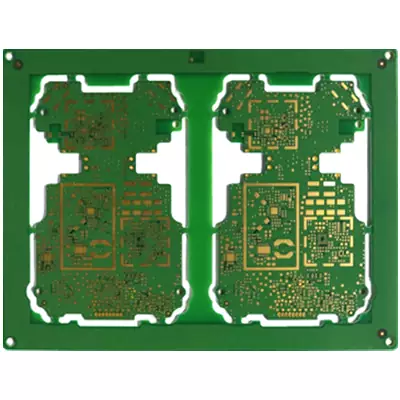
Product Name:HDI PCB
Material:Shengyi, Tuc, ITEQ, Panasonic
Thickness: 0.3-3.2mm
Copper thickness: 0.5OZ/1oz
Surface technology: Enig/Osp
Solder mask: Green/White/Black/Red/Blue
Silk screen: White
Minimum line width/spacing: 6/6mil
Minimum through-hole: Bga 2mil
Application: HDl circuit board
iPCB Corporation provides support for PCB Prototype and Electronic Manufacturing. You can request consultation or quotation for PCB, PCBA and ODM here, please contact email: sales@ipcb.com
We will respond very quickly.