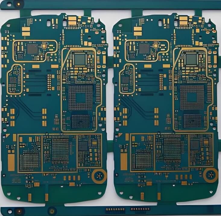
Crosstalk is a common issue in high-speed, high-density PCB designs, and it typically has a negative impact on system performance. To minimize crosstalk, the primary objective is to reduce coupling between the interfering networks and the affected networks. While it is impossible to completely eliminate crosstalk in complex, densely packed PCB designs, designers should adopt suitable methods to minimize it without compromising other system performance metrics. The following strategies are recommended to address crosstalk.

High-speed PCB
Increase Distance Between Transmission Lines: Whenever routing conditions permit, maximize the distance between adjacent transmission lines. Additionally, aim to minimize the parallel length of neighboring transmission lines, ideally routing them on different layers.
Perpendicular Routing on Adjacent Layers: For signal layers that are adjacent and lack isolation planes, ensure that the routing directions are perpendicular. This helps avoid parallel routing, which can reduce inter-layer crosstalk.
Select Low-Speed Devices: When timing permits, opt for devices with lower transition speeds. Slower changes in electric and magnetic fields can help reduce crosstalk.
Optimize Layer Stack-up: During layer stack-up design, ensure that the dielectric layer between routing layers and reference planes (power or ground planes) is as thin as possible while meeting characteristic impedance requirements. This increases coupling between the transmission lines and the reference plane, thereby reducing coupling among adjacent transmission lines.
Internal Layer Routing for Sensitive Signals: Since the top layer has only one reference plane, the electric field coupling in surface layer routing is stronger compared to mid-layer routing. Therefore, it is advisable to route sensitive signal lines on inner layers.
Implement Termination: By ensuring that the termination impedance at both ends of the transmission lines matches the characteristic impedance, you can significantly reduce the magnitude of crosstalk.