Share cost-effective products and high-quality services with customers. Contact Us


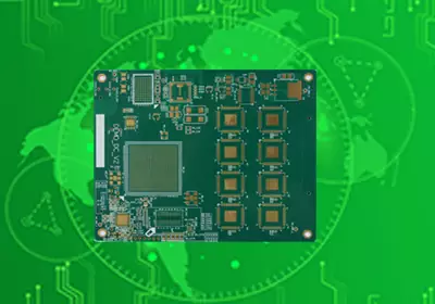
Metal Core PCB, commonly abbreviated as MCPCB or metal substrate PCBs, are circuit boards that incorporate a metal core to improve heat dissipation and mechanical stability. Conventional FR-4 PCBs use an insulating copper-clad laminate as the primary structural material, whereas metal core pcbs add a metal substrate beneath the circuit layer to provide a more efficient thermal path for dissipating heat generated by electronic components.
Metal core pcbs are commonly used in applications where heat generation can limit electrical performance, component lifetime, or overall product size. Typical applications include LED lighting, power modules, motor controllers, automotive electronics, power converters, and industrial equipment. Aluminum is the most widely used metal core material because it provides a practical balance of thermal conductivity, weight, mechanical strength, and cost. When greater heat-spreading capability is required, copper metal cores can also be used.
The complete thermal path can be summarized as follows:
Electronic Component → Copper Circuit Layer → Thermal Dielectric Layer → Metal Core → Heat Sink
This structure is the defining characteristic of an MCPCB. The purpose of adding a metal substrate is not simply to increase board strength, but to establish a controlled thermal path between heat-generating components and the external thermal management structure.
The dielectric layer plays a particularly important role because it is positioned between the copper circuit layer and the metal substrate. Its thermal conductivity and thickness directly affect the overall thermal resistance of the PCB substrate. Even when the metal core itself has excellent thermal conductivity, excessive thermal resistance in the dielectric layer can significantly limit the overall heat dissipation performance of the board.
How Metal Core PCBs Dissipate Heat
When high-power components operate, heat is generated within the semiconductor die or component package and must pass through multiple material layers before it can be dissipated into the surrounding environment.
In an MCPCB, heat is first transferred to the copper circuit layer. Copper provides electrical conductivity while also spreading heat laterally across the circuit layer. The heat then passes through the thermally conductive dielectric layer into the metal core. Compared with conventional PCB materials, the metal substrate provides a more efficient thermal path and distributes heat across a larger area before transferring it to a heat sink or equipment enclosure.
The overall thermal performance is determined by the entire thermal path rather than by the thermal conductivity of the metal core alone. Component power dissipation, copper thickness, copper coverage, dielectric thickness, dielectric thermal conductivity, metal core material, PCB dimensions, mounting configuration, heat sink specifications, and ambient temperature can all affect the final thermal performance.
Therefore, metal core pcb selection should be based on the thermal requirements of the complete system rather than simply selecting a metal material with the highest specified thermal conductivity.
Aluminum Core PCB vs Copper Core PCB
Aluminum is the most widely used metal core material for Metal core pcbs. It offers relatively low weight, good mechanical strength, readily available supply, and lower overall cost than copper. These characteristics make aluminum core PCBs widely suitable for LED lighting, power supplies, industrial control systems, and automotive electronics where improved thermal performance is required without significantly increasing product weight or cost.
Copper has substantially higher intrinsic thermal conductivity than aluminum and provides better heat spreading. When thermal management requirements are particularly demanding and the available PCB area is limited, a copper core PCB can be considered.
However, higher thermal conductivity does not necessarily make copper the optimal choice for every application. Copper has a higher density, which increases board weight and material cost, while its processing and mechanical assembly requirements can also be more demanding.
When selecting between aluminum and copper, engineers should consider the target thermal resistance, component power dissipation, operating temperature, available heat-spreading area, mechanical structure, weight limitations, and overall product cost.
MCPCB Layer Structure
The simplest metal core pcb structure consists of a single copper circuit layer, one thermally conductive dielectric layer, and a metal substrate. This configuration is widely used in LED applications because both the circuit design and thermal path are relatively straightforward.
When greater routing capacity is required, a more complex multilayer metal core pcb structure can be implemented to provide additional routing space. However, adding conductive layers increases manufacturing complexity and changes the internal thermal path of the PCB.
The copper circuit layer must provide sufficient copper area to meet current-carrying requirements while also supporting lateral heat spreading. The dielectric layer must provide reliable electrical insulation while maintaining an appropriate level of thermal resistance. The metal core must satisfy both mechanical and thermal requirements while remaining compatible with the overall manufacturing process.
The performance of all layers must therefore be optimized as an integrated system. Improving the performance of a single layer alone does not necessarily improve the overall performance of the finished PCB.

Metal Core PCB Design Considerations
Thermal design should begin with the placement and power dissipation of heat-generating components. High-power LEDs, MOSFETs, IGBTs, power diodes, voltage regulators, and other power semiconductor devices should be positioned to minimize the thermal path between the heat source and the metal core.
Copper pattern design around the heat source is equally important. A larger copper area can spread heat before it enters the dielectric layer. At the same time, the copper layout must comply with electrical design requirements, including current-carrying capacity, insulation clearance, creepage distance, and component placement constraints.
The dielectric layer is another critical design consideration. Reducing dielectric thickness can shorten the thermal path, while using a higher-thermal-conductivity dielectric can further improve heat transfer. However, the dielectric layer must still provide sufficient electrical insulation and mechanical reliability under the actual operating conditions of the product.
The interface between the metal substrate and the external heat-dissipation structure is also critical. Transferring heat into the metal core does not mean that the thermal management process is complete. Heat must still be transferred from the metal core to a heat sink, enclosure, or surrounding air. Even when an MCPCB has low internal thermal resistance, poor thermal performance at the interface can become the bottleneck of the entire thermal management system.
Mechanical performance should also be considered. The metal core, dielectric layer, and copper foil have different coefficients of thermal expansion, which can generate mechanical stress within the PCB as temperature changes. For products exposed to repeated thermal cycling, vibration, or mechanical loading, material selection and stackup design should account for these operating conditions from the beginning.
Metal Core PCBs vs FR-4 PCBs
FR-4 remains the standard PCB material for most electronic products because of its good electrical insulation, mechanical strength, processability, and cost-effectiveness.
For circuits with moderate heat generation, conventional FR-4 PCBs can often provide sufficient thermal performance through the use of copper planes, thermal vias, external heat sinks, and other thermal management techniques. The presence of power components alone does not necessarily mean that an MCPCB is required.
The advantages of metal core pcbs become more apparent when heat is highly concentrated and the PCB itself needs to provide a direct thermal path to the heat-dissipation structure. High-power LED applications and power electronics are typical examples. By reducing the thermal resistance of the PCB, an MCPCB can help control the junction temperature of semiconductor devices.
The final PCB selection should be based on thermal simulation and a complete mechanical design evaluation. Engineers should consider component junction temperature, ambient temperature, power dissipation, heat sink performance, interface thermal resistance, PCB dimensions, and available heat-dissipation area before determining the appropriate PCB structure.
Metal Core PCB Applications
LED lighting is one of the most established applications for metal core pcbs. High-power LEDs generate significant amounts of heat during operation, and excessive junction temperature can reduce luminous efficiency and shorten product lifetime. Aluminum core PCBs provide an efficient thermal path that transfers heat generated by the LED to the metal substrate and then to the external thermal management structure.
Power supply products represent another major application area. Power modules, DC-DC converters, inverters, and motor drives often concentrate multiple heat-generating components within a relatively small area. Metal core pcbs can spread heat more effectively and reduce localized temperature buildup.
Automotive electronics are also well suited to metal core PCB structures. Automotive lighting modules, motor control systems, and automotive power electronics must operate reliably at elevated temperatures while maintaining mechanical stability and effective thermal management.
In addition, metal core pcbs are used in industrial equipment, new energy systems, communication hardware, and high-power consumer electronics. The decision to use an MCPCB should ultimately be determined by the thermal requirements of the product rather than simply by the industry in which it is used.
MCPCB Manufacturing Process
The actual manufacturing process depends on the specific MCPCB stackup. A typical process includes metal substrate preparation, dielectric layer bonding or coating, copper circuit fabrication, drilling where required, solder mask application, and surface finishing, followed by electrical and mechanical reliability testing.
During MCPCB manufacturing, the bonding interface between the copper foil, dielectric layer, and metal substrate must be carefully controlled. The dielectric layer must maintain stable electrical insulation and uniform thickness to ensure predictable thermal performance.
Different materials have different physical properties, so dimensional stability is particularly important. Thermal expansion and the resulting deformation and mechanical stress must be considered during both PCB manufacturing and subsequent soldering and assembly processes.
For more complex multilayer metal core pcbs, additional conductive layers and interconnection structures increase process requirements. The stackup must be designed in coordination with the thermal path to ensure that additional circuit layers do not compromise the overall heat dissipation performance.
Advantages and Limitations of Metal Core PCBs
The primary advantage of an MCPCB is that the thermal management structure is integrated directly into the PCB board. Instead of relying solely on conventional PCB materials, thermal vias, or separate heat-dissipation components, the metal substrate provides a dedicated path for heat spreading.
The metal core can also increase the overall rigidity of the PCB board, enabling more compact thermal management solutions. In some products, this can simplify the mechanical structure of the system and reduce the space occupied by additional thermal components.
However, metal core pcbs also have limitations. Compared with conventional FR-4 PCBs, Metal core pcbs generally have higher material and manufacturing costs. The cost increase becomes more significant when specialized thermally conductive dielectric materials or copper substrates are used. The metal core also affects processes such as routing, milling, drilling, and mechanical assembly, making the manufacturing process different from that of conventional PCBs.
Circuit complexity can also be a limiting factor. Simple single-layer metal core structures are suitable for many thermal management applications, but highly complex multilayer designs may require a different PCB architecture or an alternative thermal management solution.
Metal core pcbs address concentrated heat generation in power electronics by combining a dedicated thermal path with improved mechanical rigidity. Whether an aluminum core is selected for its cost-effectiveness or a copper core is chosen for its superior heat-spreading capability, the decision should be based on the complete thermal environment and overall product cost. Only through appropriate stackup design, material selection, and manufacturing process control can the thermal advantages of Metal core pcbs be fully utilized to ensure the long-term reliability of LED lighting, power electronics, automotive systems, and other thermally demanding applications.