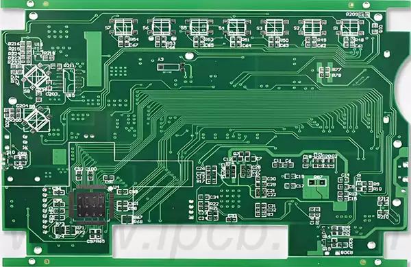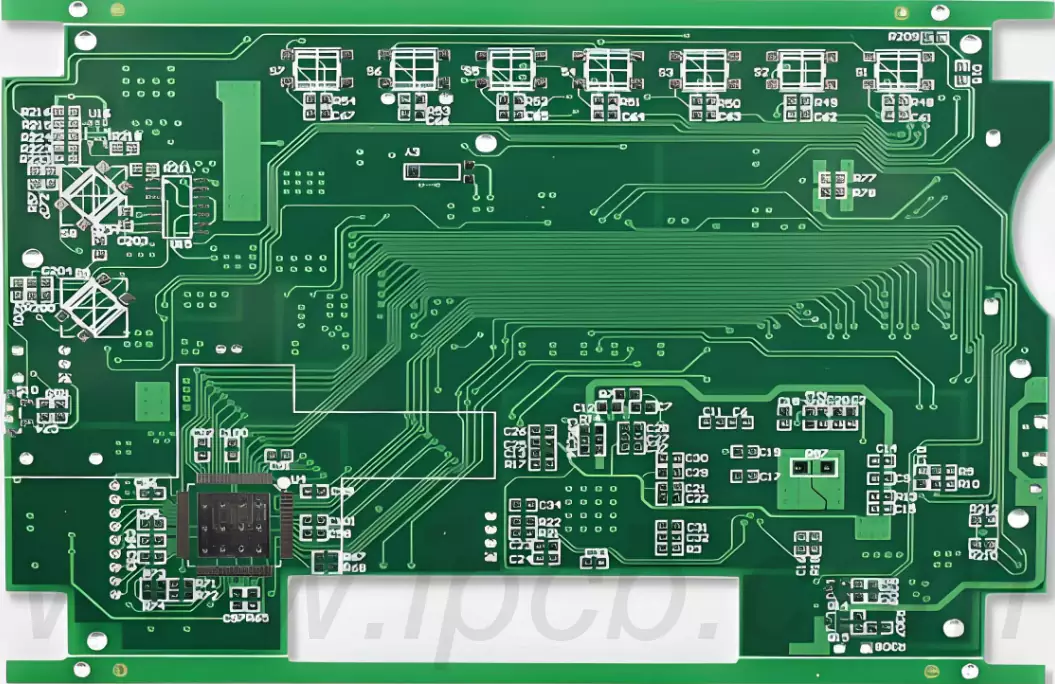
Product Name:Mobile Charger Circuit Board
Material:CCL
Thickness: 0.8mm
Copper thickness: 35um
Surface technology:Gold immersion
Solder mask: Green,Black
Silk screen: White/Green
Minimum line width/spacing: 6/6mil
Minimum through-hole: 0.4mm
Application: Mobile Charger
Mobile charger circuit board is the core part of the charger, responsible for controlling and managing the charging process. The main functions of a mobile charger pcb include voltage conversion, overcurrent protection and short circuit protection.It works by converting an AC power source (such as the power in a socket) into DC power suitable for charging the battery.Through the use of current control and voltage regulation techniques,the circuit board can effectively manage the charging process to ensure the safety and reliability of charging.
The production of mobile charger circuit board is the most important step in the whole production process. It mainly includes the following steps:
1.Topography:the designed circuit diagram is printed on the copper plate to form the line pattern.
2.Corrosion:the copper board into the acid corrosion, so that the line pattern appears.
3.Gold-plated:mobile charger circuit board surface plated with a layer of gold, play a protective and conductive role.
4.Welding:welding electronic components to the circuit board to ensure circuit connectivity.
Mobile charger pcb commonly used key materials
1.Printed circuit board substrate
The core component of a mobile charger circuit board is a printed circuit board (PCB), of which the most commonly used substrate is epoxy resin (FR-4). This material not only has excellent electrical insulation, can effectively prevent short-circuit and current leakage, but also has excellent mechanical strength, can withstand certain physical impact. In addition, epoxy is resistant to high temperatures and humidity, ensuring that the board's performance is not compromised under variable environmental conditions.This allows the charger to work reliably in extreme temperatures or humid environments, thus meeting the user's long-term use requirements.
2.Copper Cladding
The circuitry on the mobile charger pcb is generally made up of copper foil, whose good conductivity provides the basis for efficient current transfer. Typically, the surface of a mobile charger circuit board is covered with a thin layer of copper foil, usually between 1 oz (about 35 microns) and 2 oz (about 70 microns) thick, and then chemically etched to form the desired circuit pattern. High-quality copper foil not only reduces resistance and improves energy efficiency, but also reduces heat generation in the overall design, thus protecting the circuitry from damage due to overheating and ensuring the stability and safety of the charging process.
3.Capacitors and Inductors
Capacitors are key components in mobile charger pcb,they are used to store electrical energy and filter current to ensure the stability of output voltage and current.Common capacitor materials include ceramic capacitors and aluminium electrolytic capacitors,of which ceramic capacitors are widely used due to their small size, durability and low voltage characteristics. Inductors, on the other hand, are mostly designed to limit current variations and regulate current fluctuations by generating an electromagnetic field to ensure that the current flows within a set range to avoid damage to the circuit. The reliability and quality of these components have a direct impact on the overall performance of the charger.
4.Diodes and Transistors
Diodes and transistors play a vital role in the mobile charger pcb.Diodes are responsible for ensuring a unidirectional flow of current and preventing unwanted reverse currents from harming the circuit.This protection mechanism avoids circuit damage and potential safety hazards. They are generally made from semiconductor materials such as silicon or germanium, which effectively control the flow of current. Transistors, on the other hand, are more complex and are used not only for signal amplification, but also as switches to precisely control the switching of power. The selection and design of these semiconductor components greatly affects the charger's functionality and responsiveness.
5.Heat dissipation materials
As mobile phone chargers generate heat during prolonged use,the choice of heat dissipation material is critical.Effective thermal solutions usually use heat sinks or pads made of metal materials such as aluminium or copper,which not only have excellent thermal conductivity, but are also easy to process and install.Through thermal design, the charger is able to maintain a suitable operating temperature while charging efficiently,thus ensuring stable operation of the circuitry and reducing the risk of device damage due to overheating.
6.Connector and Plug Materials
The connector and plug materials of chargers are usually made of high-strength, heat-resistant plastic materials, such as nylon or polycarbonate. These materials not only provide good mechanical strength to resist wear and deformation caused by frequent plugging and unplugging, but also have high temperature resistance to ensure safe use under high loads. In addition, quality connector design can significantly reduce resistance, improve charging efficiency and reduce energy loss.
7.On-Board Protective Coating
In order to improve the weather resistance and corrosion resistance of the circuit board,the surface of the circuit board of the mobile phone charger is usually sprayed with a protective coating. These coatings are generally made of polymer materials and can effectively protect the circuit board from moisture,dust and other chemicals. With this coating, the durability of the charger is dramatically increased, and it is able to maintain good performance in different environments for a longer lifespan.

Working principle of mobile charger circuit board
Power Input
The first part of the mobile charger pcb receives AC power from the home outlet, which is usually between 100V and 240V, depending on the grid standards of the country or region where it is located. When the plug is inserted into the wall socket, the current first enters the charger and the circuit board's internal circuitry will begin to operate, with the aim of converting this high voltage electricity into a lower voltage current for subsequent processing. At this point, the mobile charger pcb processes the incoming power using capacitors and filters to eliminate high frequency noise that can affect current fluctuations and maintain current stability to ensure safe and efficient charging.
AC to DC Conversion
Next,the heart of the charger comes into play,which usually consists of a transformer and a rectifier.The transformer works by converting the incoming high-voltage AC power into low-voltage AC power by means of electromagnetic induction through coils,a process that usually involves a combination of coils designed to convert different voltages. Subsequently,a rectifier converts the transformer-processed low-voltage alternating current into direct current.In this step,diodes are used to precisely control the flow of current, ensuring that the negative half of the current is blocked and only the positive half passes, resulting in a clear DC output.The complexity of this process lies in the need to ensure that there is no excessive loss of power during the conversion process, and charger designers therefore often use highly efficient diodes to maximise power utilisation.
Voltage regulation and stabilisation
Common capacitor materials include ceramic capacitors and aluminium electrolytic capacitors, of which ceramic capacitors are widely used due to their small size, durability and low voltage characteristics.Inductors,on the other hand, are mostly designed to limit current variations and regulate current fluctuations by generating an electromagnetic field to ensure that the current flows within a set range to avoid damage to the circuit.
When the user plugs in the mobile phone for charging,the power management chip will detect the voltage status of the mobile phone battery in real time and automatically adjust the output current.Once it finds that the mobile phone battery is close to full charge, it will reduce the current to avoid overcharging and protect the battery's life. In addition, the heat dissipation design required by the voltage regulator is also extremely important,and excellent heat dissipation can prevent the circuit board from failing due to heat generation.
Protection Mechanisms
The mobile charger circuit board also has multiple safety protection mechanisms that are key to preventing potential risks.For example,overcurrent protection monitors the current in real time and cuts off the power supply when the current exceeds the safe range, preventing the current from damaging the device or the battery.Meanwhile,overvoltage protection also plays an important role. Once the voltage rises abnormally, the circuit board will cut off the power through a special protection circuit to avoid damage to the charger and the connected mobile phone.Some chargers also integrate intelligent recognition technology, which can sense one of the types of connected devices and adjust the charging rate accordingly, thus providing users with the best charging experience.
Output Connector
Finally,after this complex process, the mobile charger pcb will start to output power to the phone's battery. The output ports of the charger are very well designed, usually USB or the more advanced Type-C ports, which are not only convenient for users to connect, but also support a variety of functions such as fast charging. In addition, the charger's cables and plugs are also designed for durability and flexibility, with wear-resistant materials that can withstand repeated bending, twisting, and plugging to prolong their service life.
With its complex and delicate design, the mobile charger circuit board ensures a safe, efficient and stable charging process, while the selection of high-quality materials further enhances the durability and protection of the charger. In the future, as technology continues to advance, the charger will become more intelligent and efficient, bringing users a better charging experience
Product Name:Mobile Charger Circuit Board
Material:CCL
Thickness: 0.8mm
Copper thickness: 35um
Surface technology:Gold immersion
Solder mask: Green,Black
Silk screen: White/Green
Minimum line width/spacing: 6/6mil
Minimum through-hole: 0.4mm
Application: Mobile Charger
iPCB Corporation provides support for PCB Prototype and Electronic Manufacturing. You can request consultation or quotation for PCB, PCBA and ODM here, please contact email: sales@ipcb.com
We will respond very quickly.