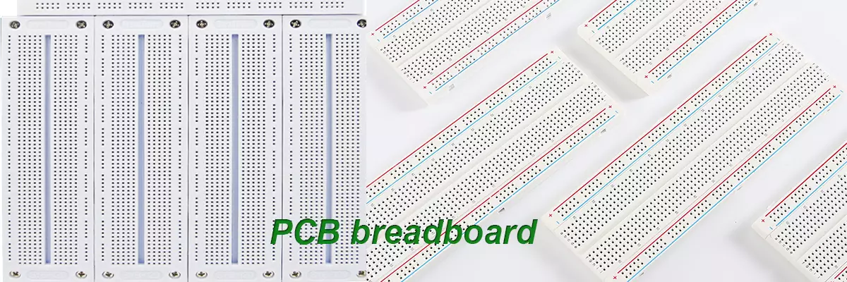
Product Name: PCB Breadboard
Material: FR-4
Thickness: 1.6mm
Copper thickness: 1/1oz
Surface technology: Glod
Solder mask: Green
Silk screen: White
Minimum line width/spacing: 6/6mil
Minimum through-hole: 0.2mm
Application: Digital products
What is PCB breadboard?
PCB breadboard is designed and manufactured specifically for solderless experiments of electronic circuits due to the many small sockets on the PCB board. Due to the fact that various electronic components can be inserted or removed as needed, eliminating the need for soldering and saving circuit assembly time, and the components can be reused, they are very suitable for the assembly, debugging, and training of electronic circuits.
The name PCB breadboard can be traced back to the era of vacuum tube circuits. At that time, most of the circuit components were large in size, and people usually fixed them on a wooden board for cutting bread with screws and nails for connection. Later, the size of circuit components became smaller and smaller, but the name PCB breadboard was still used.
How to use PCB breadboard?
PCB breadboard does not require soldering or manual wiring. Simply insert the components into the holes to test the circuit and components, making it easy to use. Before use, it is necessary to determine which components' pins should be connected together, and then insert the pins to be connected together into the 5 small holes in the same group.

PCB breadboard classification
Solder free PCB breadboard
A solderless PCB breadboard is a motherboard that does not serve as a base and does not have a soldered power outlet, but can be extended to a single PCB breadboard. Before use, power should be turned on first. Connect the two poles of the power supply to the sockets on both sides of the breadboard, and then you can plug in the components for the experiment (disconnect the power supply during the insertion process). When encountering more than 5 components or a set of sockets that cannot be plugged in, it is necessary to use PCB breadboard connection wires to connect multiple sets of sockets together.
The advantages of solderless PCB breadboard are small size and easy portability, but the disadvantages are relatively simple, inconvenient power connection, and small area. It is not advisable to conduct large-scale circuit experiments. To conduct large-scale circuit experiments using it, multiple PCB breadboard need to be fixed to a large wooden board with screws and connected with wires.
Single PCB breadboard
A single PCB breadboard is a PCB breadboard with a motherboard as the base and dedicated terminals for power connection. Some even have grounding terminals for high-voltage experiments. This type of PCB breadboard is relatively convenient to use. Simply connect the power supply to the terminal post and insert the components for experimentation (disconnect the power supply during the insertion process). When encountering more than 5 components or a set of sockets that cannot be plugged in, PCB breadboard connecting wires are needed to connect multiple sets of sockets together.
Combination PCB breadboard
A combination PCB breadboard is a PCB breadboard made by combining many solderless breadboard together. Generally, 2-4 solderless PCB breadboard are fixed on the motherboard, and then the power lines of each PCB breadboard are connected together using copper foil inside the motherboard. The professional combination PCB breadboard has also designed separate power control for different circuit units, allowing each PCB breadboard to carry different voltages according to user needs. The use of a combination PCB breadboard is the same as that of a single PCB breadboard.
PCB board vs PCB breadboard
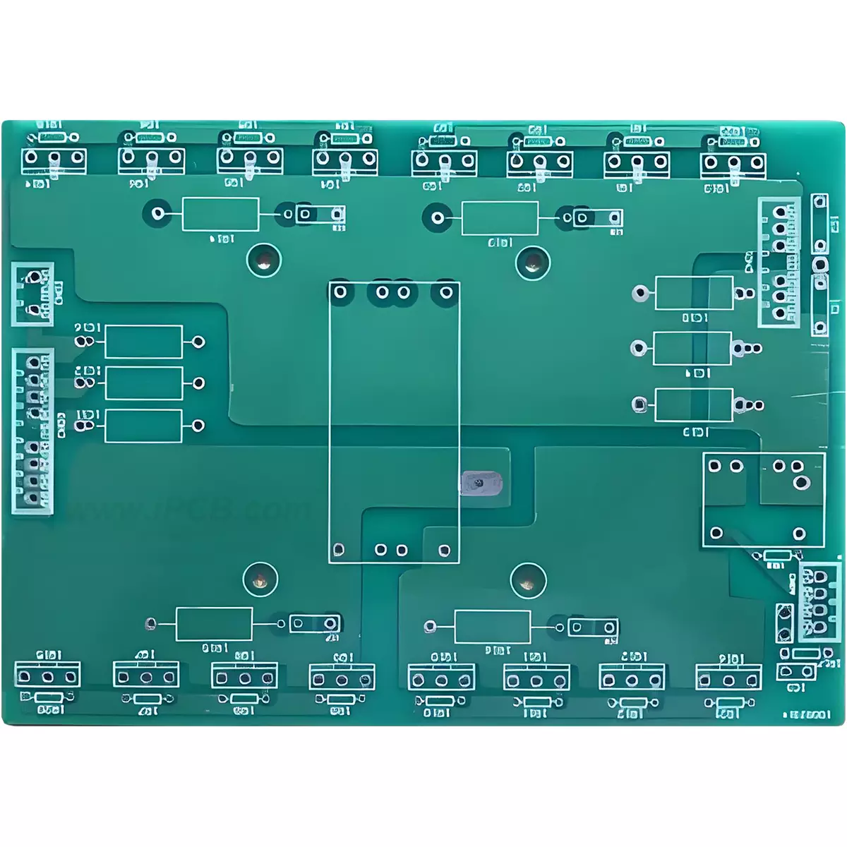
PCB board: The use of PCB board requires certain professional knowledge and skills. PCB board designers need to first use circuit design software to draw a circuit diagram, and then convert the designed circuit diagram into the layout of conductive lines and components on the PCB. Afterwards, a series of processing techniques such as printing, etching, drilling, etc. are used to produce the finished PCB board. Finally, solder the components onto the PCB board to complete the circuit setup.
PCB breadboard: When using PCB breadboard for circuit construction, simply insert the component pins into the corresponding small holes without soldering. This method is very suitable for temporary circuit testing and small-scale prototyping.
PCB breadboard and PCB board each have their own applicable scenarios and advantages and disadvantages. For beginners and small-scale prototyping, PCB breadboard is a convenient and low-cost option. For the design and production of complex circuits and large-scale production needs, PCB board is a more professional and reliable choice.
Product Name: PCB Breadboard
Material: FR-4
Thickness: 1.6mm
Copper thickness: 1/1oz
Surface technology: Glod
Solder mask: Green
Silk screen: White
Minimum line width/spacing: 6/6mil
Minimum through-hole: 0.2mm
Application: Digital products
iPCB Corporation provides support for PCB Prototype and Electronic Manufacturing. You can request consultation or quotation for PCB, PCBA and ODM here, please contact email: sales@ipcb.com
We will respond very quickly.