Share cost-effective products and high-quality services with customers. Contact Us


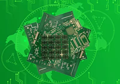
A PCB stiffener is a mechanical reinforcement component attached to a designated area of a flexible printed circuit board (FPC) to increase local rigidity, control the finished thickness, and provide mechanical support for connectors, electronic components, or contact areas. Unlike copper foil layers or circuit routing layers, a stiffener generally does not carry electrical signals. Its primary purpose is to modify the mechanical properties of a specific area of the flexible circuit so that the FPC can meet the mechanical requirements of the final assembly.
PCB stiffeners are primarily used with flexible printed circuits because an FPC typically needs to remain flexible over most of its surface, while certain areas, such as connector interfaces, SMT component mounting areas, mounting holes, and contact points, require additional rigidity. By applying a stiffener only to these designated areas, the required mechanical support can be achieved without making the entire flexible circuit rigid.
Why Are PCB Stiffeners Used?
The fundamental purpose of a flexible printed circuit is to provide flexibility, but not every section of an FPC needs to have the same degree of flexibility. Connector interfaces, component soldering areas, and locations subjected to repeated insertion, removal, or mechanical loading generally require greater mechanical stability. In these areas, excessive flexibility can lead to deformation during assembly or operation and can transfer unwanted mechanical stress to solder joints, copper conductors, and other components.
One of the most typical applications is the tail section of an FPC that connects to a ZIF connector. When the flexible circuit is inserted into a ZIF connector, the exposed contact area must maintain a precisely controlled finished thickness so that it can properly engage with the connector contacts. A polyimide (PI) stiffener can be bonded to the back side of the gold fingers to increase the local thickness while keeping the rest of the flexible circuit thin and flexible. Common ZIF interface thickness specifications are approximately 0.2 mm and 0.3 mm, although the final required thickness must always be determined according to the connector manufacturer's specification.
Stiffeners are also widely used underneath SMT components and connectors. During component placement, reflow soldering, assembly, transportation, and handling, an FPC can be more susceptible to deformation than a rigid PCB. If the flexible circuit bends around a soldered component, the resulting mechanical stress can be transferred directly to the solder joints and copper conductors. An FR-4 stiffener provides a locally rigid support structure that helps prevent unintended bending of the circuit around the component and improves the mechanical stability of the assembly.
The important point is that a stiffener is a localized reinforcement structure. Its purpose is not to make the entire FPC rigid, but to reinforce only those areas where the inherent flexibility of the circuit could otherwise create mechanical or assembly-related reliability problems.
PCB Stiffener Materials and Thickness Selection
The most commonly used PCB stiffener materials include FR-4, polyimide (PI), stainless steel, and aluminum alloy. These materials provide different levels of rigidity, thickness, weight, thermal conductivity, and compatibility with flexing requirements, so the appropriate material must be selected according to the mechanical and assembly requirements of the specific application.
FR-4 stiffeners are commonly used when relatively high rigidity is required. They are particularly suitable for SMT component mounting areas and connector locations where the flexible circuit needs a firm mechanical support surface. FR-4 stiffeners are available in a wide range of thicknesses, with approximately 0.2 mm to 1.6 mm being a common range in the industry. The actual available thicknesses depend on the PCB manufacturer and the requirements of the product.
Polyimide (PI) stiffeners, commonly referred to as Kapton® in commercial applications, are suitable when a thin reinforcement structure is required. They are frequently used on the back side of FPC gold fingers for ZIF connector applications because they can provide additional thickness and rigidity without significantly increasing the overall thickness of the flexible circuit. Common production PI stiffener thicknesses are approximately 0.1 mm to 0.25 mm, although specifications vary among suppliers.
Stainless steel stiffeners can provide a high level of mechanical strength even when the available installation space is limited. They are therefore suitable for applications that require high rigidity within a relatively thin structure or where the FPC is exposed to significant mechanical loading. However, stainless steel is electrically conductive, so the design must provide sufficient electrical clearance and appropriate insulation to prevent unintended electrical contact with conductors, pads, or other conductive structures.
Aluminum alloy stiffeners can provide mechanical reinforcement and may also contribute to thermal conduction. However, aluminum should not be selected simply because it has high thermal conductivity. Its actual thermal benefit depends on the complete thermal design of the electronic assembly, including the heat source, heat path, interface materials, and external heat dissipation structure.
The thickness of a PCB stiffener should never be determined independently from the FPC stack-up. The finished thickness of the reinforced area is determined by the combined thickness of the FPC base material, copper foil, coverlay, adhesive layers, and stiffener. In practical terms, the local finished thickness can be considered as:
Finished Thickness = FPC Construction + Adhesive Layer(s) + Stiffener
For connector tails, the primary thickness constraint is normally determined by the connector specification and its allowable contact thickness. For SMT support areas, the required stiffener thickness depends on the required rigidity, component height, enclosure clearance, assembly method, and mechanical loading during operation.
A thicker stiffener does not necessarily provide better performance. Excessive thickness can interfere with connector insertion and mating, increase mechanical stress at the transition between the stiffened and flexible sections, reduce the available bending area, and potentially introduce additional mechanical fatigue during repeated flexing.
PCB Stiffener Layout Is a Critical Design Consideration
The location of a PCB stiffener is just as important as the selection of the stiffener material and thickness. A stiffener should generally be positioned outside the dynamic bending area of the FPC. The transition between the reinforced section and the flexible section needs to be designed carefully so that the mechanical load is distributed gradually rather than concentrated at the edge of the stiffener.
If the edge of a stiffener is positioned too close to a bending area, it can become a stress concentration point. During repeated bending, the rigid edge can transfer excessive mechanical stress to the flexible copper conductors and dielectric layers, potentially resulting in conductor fatigue, copper cracking, delamination, or other reliability failures.
This consideration is particularly important for dynamic-flex applications. An FPC that is bent only once during final assembly has fundamentally different mechanical requirements from an FPC that is repeatedly bent or folded throughout the operating life of the product. For dynamic-flex applications, the bending radius, number of bending cycles, bending direction, and location of the stiffener edge should all be considered during the mechanical design stage.
The outline of the stiffener must also be checked against components, solder pads, vias, mounting holes, coverlay openings, and connector structures. A common manufacturing problem occurs when the stiffener outline is defined without reviewing the layout on the opposite side of the FPC. If the mechanical drawing and electrical layout are not reviewed together, the stiffener may interfere with a solder pad, component, via, or other structure located on the opposite side of the flexible circuit.
For this reason, all stiffener information should be clearly defined in the PCB fabrication documentation. The fabrication drawing should specify the stiffener material, thickness, attachment side, outline dimensions, bonding method, and applicable dimensional tolerances. Clear and complete documentation allows the PCB manufacturer to correctly interpret the reinforcement requirements and reduces the risk of manufacturing errors.

PCB StiffenerManufacturing Process in FPC Production
PCB stiffeners are generally bonded to the flexible substrate after the primary circuit fabrication processes have been completed. Depending on the construction of the FPC and the application requirements, manufacturers may use pressure-sensitive adhesive (PSA), thermosetting adhesive, or other bonding systems that are compatible with the flexible substrate and the selected stiffener material.
Bonding accuracy is particularly important because the stiffener is often positioned in direct relation to an external component or mechanical interface. For example, a stiffener applied to an FPC connector tail must be accurately aligned with the exposed gold fingers so that the finished contact thickness and mechanical position meet the connector requirements. Similarly, an FR-4 stiffener used to support SMT components must be positioned so that it does not interfere with solder pads, component placement, or other assembly features.
The bonding process also has a direct effect on the final thickness and dimensional stability of the reinforced area. When a stiffener is used in a connector application, the thickness calculation should include the entire bonded structure rather than considering only the nominal thickness of the stiffener itself. The adhesive layer can contribute a measurable amount to the final thickness and may affect connector compatibility when the allowable thickness tolerance is tight.
Because adding a stiffener introduces additional materials, bonding operations, and manufacturing costs, it should only be used where mechanical reinforcement is actually required. If an FPC does not require a connector interface, does not carry SMT components, and is not exposed to significant mechanical loading, a stiffener may not be necessary.
Typical Applications of PCB Stiffeners
PCB stiffeners are widely used in flexible electronic assemblies where certain areas of the FPC require additional mechanical support. The gold-finger tail used with a ZIF connector is one of the most common applications because the contact area must have both a precisely controlled finished thickness and sufficient rigidity for reliable insertion and electrical contact.
Another major application is an FPC that carries surface-mount components. An FR-4 stiffener bonded to the back side of the component mounting area provides a more stable support platform during component placement, reflow soldering, and subsequent assembly operations. It also helps reduce deformation of the flexible circuit and mechanical stress around solder joints. This configuration is particularly useful when two rigid PCBs are interconnected by an FPC and electronic components must be mounted directly on a section of the flexible circuit.
Stiffeners may also be applied around mounting holes, battery interfaces, board-to-board connector areas, display FPCs, camera modules, sensor assemblies, and various small precision electronic devices. In each case, the stiffener is intended to solve a specific mechanical problem rather than simply increase the overall strength of the entire flexible circuit.
For applications involving limited installation space or relatively high mechanical loads, metal stiffeners may be selected when FR-4 or PI cannot provide the required mechanical performance. Metal stiffeners can also be designed as segmented reinforcement structures, allowing engineers to control the transition between rigid and flexible areas more precisely.
PCB Stiffener Design Considerations
When an FPC is designed for a ZIF connector, the first step is to review the connector manufacturer's datasheet and determine the required finished thickness of the contact tail. The target thickness should be based on the actual connector specification rather than on the nominal thickness of the selected PI stiffener or any other individual material.
When a stiffener is intended to support SMT components, the mechanical loads associated with component placement, soldering, assembly, handling, and normal product operation should be evaluated. The designer should determine how much local rigidity is required and select the stiffener material and thickness accordingly.
For products that undergo repeated bending, the dynamic bending area should first be identified. The stiffener should then be positioned outside this area so that the reinforced structure does not restrict the required bending movement or introduce excessive stress at the rigid-to-flex transition.
The complete local stack-up should also be evaluated, including the flexible substrate, copper foil, coverlay, adhesive layers, and stiffener. Connector compatibility and mechanical performance are determined by the total finished thickness of the complete structure rather than by the nominal thickness of the stiffener alone.
Designers should also pay close attention to the geometry of the transition between the reinforced and flexible sections. A large or sharply defined stiffener edge can significantly change the local bending behavior and create a concentrated stress region. The stiffener geometry should therefore be designed according to the actual operating conditions, with the primary objective of preventing the flexible copper conductors from being subjected to excessive bending or tensile strain at the rigid edge.
All stiffener requirements should be clearly specified in the PCB fabrication drawings so that the PCB manufacturer can accurately verify the material, thickness, location, bonding side, outline, and bonding method. Incomplete or ambiguous specifications can result in incorrect stiffener placement, excessive finished thickness, component interference, or other manufacturing defects.
PCB Stiffener vs. Rigid-Flex PCB
An FPC with a stiffener should not be confused with a rigid-flex PCB. Although both solutions combine flexible and rigid areas within an electronic assembly, their construction and electrical characteristics are fundamentally different.
A stiffener is a mechanical reinforcement component bonded to a specific area of an FPC. Outside the reinforced area, the circuit remains flexible, and the stiffener itself generally does not form part of the electrically functional PCB layer stack-up. Its purpose is primarily to provide localized mechanical support or to achieve a specified local thickness.
A rigid-flex PCB, in contrast, is an integrated PCB construction in which the rigid and flexible sections are incorporated into the same multilayer structure during the manufacturing and lamination process. Both the rigid and flexible sections can contain electrical circuitry, copper layers, vias, and interconnections as required by the design.
In simple terms, an FPC with a stiffener is appropriate when the product requires localized mechanical reinforcement, while a rigid-flex PCB is more appropriate when the product requires an integrated structure containing both rigid and flexible circuit sections with electrical interconnections between them.
Common PCB Stiffener Failure Modes
Many stiffener-related failures occur because the stiffener is treated simply as a requirement for additional thickness or rigidity rather than as part of the overall mechanical design of the FPC.
If the stiffener is too thick, it may prevent proper connector insertion or mating. If it is too thin, it may not provide sufficient mechanical support for the intended application. Incorrect placement can also reduce the available bending area and create excessive stress at the transition between the rigid and flexible sections.
Another common problem is failing to include the adhesive layer when calculating the finished thickness. Although the nominal thickness of the stiffener may meet the specified value, the actual finished thickness can exceed the connector's allowable tolerance after the adhesive layer is included in the bonded structure. This can result in connector interference or unreliable contact.
Interference with components and solder pads is another potential manufacturing issue. The stiffener design should be checked against the FPC layout on both sides, particularly when components are mounted on both sides of the flexible circuit. This cross-check is important because a stiffener located on one side may overlap with a component, pad, via, or other feature on the opposite side.
For dynamic-flex applications, the relative position of the stiffener edge and the bending zone is one of the most important design considerations. The stiffener must establish a controlled mechanical boundary without transferring excessive bending or tensile strain to the flexible copper conductors. Proper control of this transition is essential for preventing premature conductor fatigue and improving the long-term reliability of the FPC.
PCB stiffeners provide localized mechanical reinforcement for flexible printed circuit boards while allowing the remaining areas of the FPC to retain their required flexibility. They are particularly useful in ZIF connector tails, SMT component mounting areas, board-to-board interfaces, mounting locations, and other regions where additional rigidity or precise local thickness control is required.
Selecting the appropriate stiffener requires more than simply choosing a material and thickness. The complete FPC stack-up, adhesive thickness, connector tolerance, stiffener geometry, component clearance, rigid-to-flex transition, bending radius, and dynamic-flex requirements all need to be considered as part of the overall mechanical design.
When properly designed and manufactured, a PCB stiffener can provide the localized mechanical support required by an FPC while preserving flexibility in the areas where bending and movement are necessary. This makes stiffeners an effective and cost-efficient reinforcement solution for a wide range of flexible electronic assemblies.